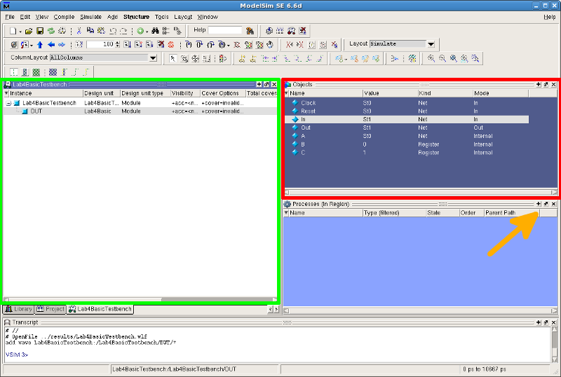
Hence, we have to instantiate our design module to the test module. The purpose of a testbench is to verify whether our DUT module is functioning as we wish. Wire C //think of this as the output DUT Instantiation used upper case for signals to avoid confusion We can declare these data types for the testbench of the AND module. This is used to check the output signals from the DUT. This data type cannot be used in initial or always blocks. It will hold the value that is driven by a port, assign statement, or reg. The wire datatype is similar to that of a physical connection. You can read more about the reg datatype in Verilog here. This is used to apply a stimulus to the inputs of DUT. This data type can be assigned a value only in the always or initial block. The reg datatype will hold the value until a new value is assigned to it. But, in a testbench, we will use two signal types for driving and monitoring signals during the simulation. Usually, we declare the input and output ports. module and_gate_test_bench ĭid you notice something? Yes. Like any Verilog code, start with the module declaration. Consider the AND module as the design we want to test. Let’s learn how we can write a testbench.

This article will help you to take your first steps in writing testbenches.
#Modelsim testbench verilog verification
In fact, in our post on introduction to VLSI, we mentioned that a Verification Engineer is a separate position that’s pretty common in the semiconductor industry.īut don’t worry. Verifying a system can take up around 60-70% of the design process.

Writing a test bench is a bit trickier than RTL coding.

With a testbench, we can view all the signals associated with the DUT.


 0 kommentar(er)
